Flow measurement - What you should know
Along with temperature and pressure measurement, flow measurement is one of the most important tasks of industrial measurement technology and can be performed using various methods. The application areas and applications vary greatly and place different requirements on flowmeters. Find out more about the measurement methods and the underlying technologies!
Table of contents
What is a flow measurement?
The flow measurement is a method of determining a quantity of liquid, gas, or steam flowing through a pipe or duct. It is mainly used for industrial process control and monitoring, ensures process efficiency and reduces downtime as well as energy and material losses. It is often referred to as flow measurement technology or flow technology.
Why does the flow need to be measured?
In flow technology, sensors are used as switches or continuous measuring devices. Both functions are also often combined in the flow device. The switches are used, for example, as dry-run protection for pumps. The sensors for continuous measuring tasks are intended, among other things
- For filling end products in bottles, containers, or tanks
- For monitoring or displaying the totalized flow rate in the process.
- For custody transfer in dispensers, as hot and cold water meters, etc.
What are the requirements for flow measurement?
The requirements for the flow device vary greatly depending on the measurement task. Good repeatability is required for filling, and in custody transfer a type examination certificate is necessary, at least in the EU. There are also any number of requirements for monitoring and displaying the totalized flow rate in the process, due to a specific application or industry. These include, among other things, the operating conditions, an on-site installation, but also legal requirements such as the Pressure Equipment Directive in the EU or explosion protection according to the ATEX directive.
Which media does a flow sensor measure?
The media are divided into 4 different categories:
- Conductive liquids (>20 μS/cm): acids, bases, beer, milk, drinking water, etc.
- Non-conductive liquids: alcohols, glycols, mineral-oil-based liquids, deionized water, etc.
- Gas: oxygen, nitrogen, compressed air, natural gas, etc.
- Steam: saturated steam, overheated steam
Totalized flow rates for solids are also measured using various methods. However, this will not be considered further here.
What are the measurement methods in the flow measurement?
Flowmeters make use of different physical measurement principles that can only measure in certain categories depending on their nature. In addition, a distinction is made between modern and traditional measurement methods when it comes to flow measurements - as listed in the table below. This is not an evaluation; traditional measurement principles still have their raison d'être in many areas.
|
|
|
||||||
|
|
|
|
|
|
|
|
|
| Conductive liquid | |||||||
| Liquid | |||||||
| Gas | |||||||
| Steam | |||||||
Green = standard; Orange = use caution; Red = not possible or recommended
The table only shows the physical application possibilities in the respective media, but does not address individual requirements. Further information on the different flow-through methods is available in the video.
Coriolis flow measurement
Flow measurement technology based on the Coriolis principle is used to measure the mass flow of gases or liquids passing through. The flowmeter consists of 1 or 2 metallic pipes in the form of a semicircle or full circle, bend, or delta shape. Single-pipe systems are used especially for the hygienic industry.
Coriolis flowmeters are considered the most accurate inline flowmeters on the market, with specifications starting at 0.05 % of the measured value. The accurate measuring systems divide the total flow into 2 systems, so there is an increased pressure drop compared to a single-pipe system.
Mathematically, it can be demonstrated that the vibrating pipe of the Coriolis flowmeter is equivalent to a circular motion. This means that the flowing mass in the pipe is equivalent to the body moving in a circular motion. This creates a force orthogonal to the direction of flow, called the Coriolis force, which acts on the pipe. However, the resulting force is only determined indirectly. In practice, the phase shift of the pipe vibration from inlet to outlet is measured. Furthermore, the frequency of the measuring pipe can be determined. The following relationships exist for mass flow and density:
ṁ ~ Δ φ
ρ ~ 1/√(mpipe+mFl)
The volume flow can be calculated from this:
V̇ = ṁ/ρ
| Coriolis flowmeter | |
|---|---|
| Advantages | High level of accuracy, multi-parameter, no inlet and outlet sections |
| Disadvantages | High costs, pressure loss (especially for two-pipe systems), sensitive reaction to gas bubbles in liquid media |
Electromagnetic flow measurement
An electromagnetic flowmeter (EMF) measures according to Faraday's law of electromagnetic induction. It consists of a metal measuring pipe through which a conductive medium flows and which is provided with a magnetic field generated by coils.
A voltage is induced as soon as the conductive liquid moves through the orthogonal magnetic field. The induced voltage is determined via electrodes which are arranged at a 90° angle to the liquid and the magnetic field (three-finger rule).
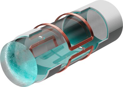
Electromagnetic flowmeter
The device therefore measures a velocity which, when multiplied by the cross-sectional area, gives the volume flow. The prerequisite is therefore a completely filled pipe. The corresponding formula is:
v ~ U ind
| Electromagnetic flowmeters | |
|---|---|
| Advantages | High level of accuracy, no pressure loss, no/low inlet and outlet sections, flexible application possibilities |
| Disadvantages | High costs, only for conductive media |
Ultrasonic flow measurement
For the ultrasonic flow measurement, 2 different physical principles are mainly used: the transit time principle and the Doppler principle. The market is dominated by the transit time principle. Therefore, the Doppler principle or the combination of both principles will not be discussed here.
Ultrasound is a mechanical or acoustic wave that is decelerated against the current and accelerated with the current. For flow measurements with ultrasound, the different transit times (with and against the flow) are measured for the same section. The difference between the 2 times is the measure of the flow velocity. In order to measure the time difference, 2 transducers are needed as "loudspeaker" and "microphone". The volume flow is calculated by multiplying the velocity and the pipe cross-section.
V ~ △ t
| Ultrasonic flowmeters | |
|---|---|
| Advantages | Accuracy, low pressure drop (depends on mechanical implementation of pipe/transducer), short inlet and outlet sections |
| Disadvantages | Accuracy dependent on flow profile, solid particles + gas bubbles |
Vortex flow measurement
The vortex measuring principle is based on the Kármán vortex street, in which a body with a flow around it causes counter-rotating vortices to occur. In practice, alternating, counter-rotating vortices are created in the flowing medium by introducing an obstruction into the pipe. These form local pressure differences, which are acquired by an appropriately designed sensor. The sensor measures the number of vortices per time unit, i.e. the frequency of the vortices that occur.
v ~ ƒ
However, this linear relationship is only present for high Re numbers (>10000).
| Vortex flowmeters | |
|---|---|
| Advantages | Possible for liquids, gases + steam, high pressures + temperatures, cost-effective variants available |
| Disadvantages | Only water-like viscosities possible, no "low flow" applications |
Calorimetric flow measurement
The method uses 2 Pt100 sensors, 1 of which is used as a heating element and the other as a sensing element for the medium temperature. The temperature difference between the heating Pt100 and the medium is kept constant and the heat output required for this is measured. The higher the flow of the medium, the more heat output is required to keep the temperature difference constant. In this way, conclusions can be drawn about the respective totalized flow rate through the heat output.
The context of a flow sensor looks like this:
v = ƒ (Ṗ)

Calorimetric flowmeter
| Calorimetric flowmeter | |
|---|---|
| Advantages | Cost-effective sensor technology for gas + liquid, leakage measurements possible |
| Disadvantages | Adhering pollutants/moisture (with gas) influence measurement, accuracy with "low-cost" solutions rather low + medium-dependent |
Flow measurement with differential pressure/primary element
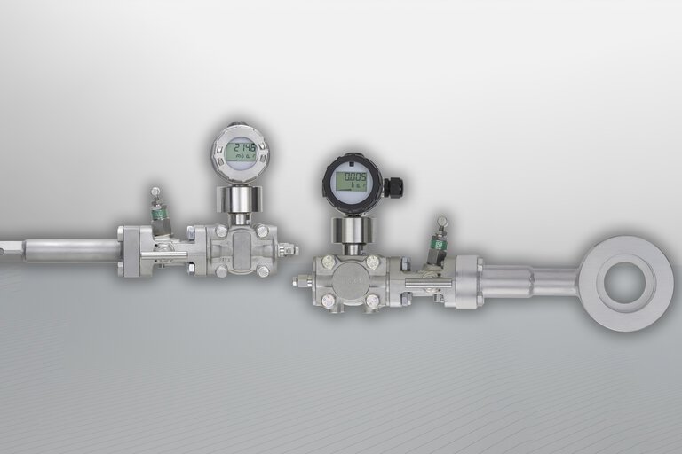
Primary elements include orifice plates, pitot tubes, Venturi tubes. Installed in the pipe, they generate a differential pressure, which is measured, for example, in the orifice plate via the static pressure upstream and downstream of the orifice plate. This can be converted into a velocity using the Bernoulli formula.
The context is as follows:
v ~ √(△p÷ρ)
Appropriate differential pressure sensors are required to measure the differential pressure. The accuracy is thereby composed of the uncertainty of the primary element and the differential pressure transmitter, provided that the density p is constant.

Primary element
| Primary element | |
|---|---|
| Advantages | High temperatures + pressures possible due to mechanical flexibility of the primary element, for gas, liquid + steam |
| Disadvantages | Limited measuring dynamics (1:5 to 1:7; ratio of max to minimum flow), unfavorable accuracy/cost ratio for small diameters |
Paddlewheel flow measurement
The paddlewheel is rotated by the flow of the medium; this rotation is transmitted without contact and without feedback to a pulse generator controlled by magnetic field and mounted on the housing. The rotary motion is converted into a frequency signal proportional to the flow. This frequency can be processed directly or by downstream electronic components pertaining to the flow measurement. The corresponding formula is
v ~ ƒ

Paddlewheel flow sensor
| Flügelrad-Durchflussmesser | |
|---|---|
| Advantages | Cost-effective design types available, flexible use of materials enables measurement of corrosive media |
| Disadvantages | Low flow application only possible to a limited extent due to start-up friction, moving parts can cause wear |
How do you choose the right sensor for the flow measurement?
The measuring principle must be suitable for the medium - as described above. Other requirements that a flow device must meet include:
- Operating conditions (flow range, pressure, temperature, material compatibility)
- Installation conditions (inlet/outlet section, pipe routing, installation)
- Environmental influences (temperature, moisture, vibrations)
- Legal requirements (explosion protection, calibration obligation)
The choice is further complicated by broader practical constraints:
- Solid or gas content
- Non-optimal installation situation
- Cost versus accuracy
Due to these different challenges, expert consulting on the choice of flowmeter is essential.
- ${title}${badge}
